Experience with Online Monitoring of Capacitance
Experience with Online Monitoring of Capacitance and Tangent Delta of Condensive Bushings
- 30/01/2013
- Transmission
Abstract
Capacitance and tangent delta are acknowledged as some of the main parameters for bushing insulation condition diagnosis, because they are directly affected by the deterioration of the insulation. This article intends to display a technique used in on-line monitoring of capacitance and tangent delta of bushings, in addition to an actual field deployment experience in monitoring 550kV and 245kV bushings on auto-transformers and power reactors.
Results shown were obtained during the course of approximately one year, including on-line detection of insulation deterioration for a 550kV bushing, avoiding a possible failure with explosion, later proven by off-line measurements of capacitance and tangent delta and by gas-chromatography analysis of oil sample from the bushing.
Additionally, some practical consideration about practical issues related to installing online bushing monitoring systems on transformers equipped with Bushing Potential Devices (Dispositivos de Potencial de Bucha – DPB), where the tap of the bushing is already occupied, as well as on equipment on which it was possible to make the connection directly to the tap of the bushing.
| Furnas Centrais Elétricas S.A. | Marcos A. C. Melo |
| Treetech Sistemas Digitais Ltda. | Marcos E. G. Alves |
1.0 – INTRODUCTION
In spite of being an accessory to the different types of equipment mentioned, and in general, at relatively low unit costs as compared to the overall cost for the entire equipment, condenser bushings perform an essential function in operating high voltage equipment, like power transformers and shunt reactors.
On the other hand, bushings are subjected to material dielectric efforts, considering it are the first equipment to receive eventual overvoltage resulting from maneuvers, atmospheric discharge impulses or other phenomenon with similar outcomes. A failure on their insulation can be reflected in damage not only to the bushing, but also to the equipment to which it is associated. In extreme cases, a dielectric failure in the bushing can lead to total destruction of the high voltage equipment, in addition to the risk for people close to it.
In avoiding this type of event, energy utility companies traditionally deploy time-based preventive maintenance programs, removing the equipment from service periodically for off-line measurements capacitance and tangent delta of bushing insulation. Taking as example standard ANSI/IEEE C57.19.100-1995 (1), typical recommended maintenance interval is of 3 to 6 years between readings. However, this maintenance philosophy offers the following main disadvantages:
- The possibility of defects developing in a period between two readings, possibly leading to severe failures,
- The need to disconnect and de-energize the equipment in order to perform reading procedures, leading to costs for non-availability and reducing the overall reliability of the electrical system, and
- Deployment of maintenance engineering teams, usually with low headcounts, in performing tests.
In the case of Furnas, the regular period foreseen in the company maintenance plan for these readings was of 6 years. However, in the case of the Serra da Mesa Generation Plant, suspicion in relation to a given bushing family led to the need for a reduction in the length of the maintenance periods between off-line readings to only 3 months in a bank of single-phase 133.33MVA 550/245/13.8kV transformers and a bank of single-phase 55MVAr 550kV reactors, thus raising materially maintenance and system unavailability costs.
The alternative used to overcome these disadvantages of time-based maintenance is on-line capacitance and tangent delta monitoring of bushings, which allows these readings to be taken continually and during the regular operation of the equipment. In this way, in November/2005, a Treetech, BM bushing monitoring system was installed on the equipment for on-line monitoring of bushing capacitance and tangent delta.
2.0 – ON-LINE BUSHING MONITORING
2.1 – Constructive details of condenser bushings
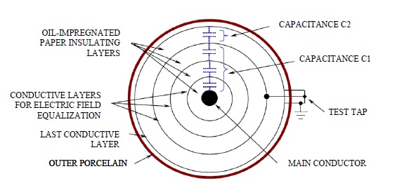
The insulation body in condenser bushings is comprised of several, concentric, cylindrical layers of insulation material staggered as shown in Figure 1ª – for the purpose of affording maximum electrical field uniformity. The outermost conductive layer is connected to the flange of the bushing that, in its turn, is connected to ground. Intermediate conductive layers, on the other hand, remain insulated, with floating potential, except for one of the outer ones that is grounded through a removable connection close to the base of the bushing, called voltage or test tap (Figure 1). For outdoor deployment, This set, called the condenser body, is encased in waterproof casing, which can be made of porcelain, silicone or silicone based polymer material.
Figure 1 – Constructive details of a condenser bushing
The above described construct acts a set of capacitors connected in series, creating a capacitive voltage splitter. This way, total difference of potential for the main lead in relation to ground is divided among the different capacitors.
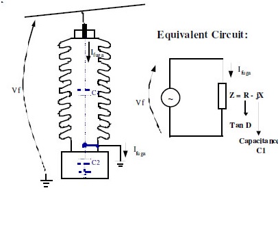
Figure 2 – Equivalent circuit for energized condenser voltage
When the phase-ground voltage is applied to the bushing, a current, called leakage current, starts to circulate through the insulation, in particular due to its capacitance, and in much lower proportion due to their dielectric losses (expressed by the dissipation or tangent delta factor). Figure 2 shows this situation; in this figure we can observe that the electrical equivalent circuit obtained from the construct shown in Figure 1, already with the bushing under tension. This is the “series” equivalent electrical model. A “parallel” electrical model could also be applied, with the same results. With a model adopted, we will have the following resulting leakage current:
Where “R” represents the resistive component of the insulation impedance, that generates the resistive portion of the leakage current, associated to dielectric losses, with “X” being the reactive component due to the capacitance of the insulation.
2.2 – Operation philosophy for on-line monitoring
The objective of on-line monitoring of condenser bushings is detecting changes in the insulation of the bushing while still in the early stages, indicating the development of conditions that may lead to dielectric failure of the equipment. In order to do this, it is necessary to detect, with the bushing energized, changes in the insulation’s capacitance and tangent delta, i.e., changes in the “Z” impedance of the insulation f the bushing.
In each of the bushings, the leakage current (Ifuga) flows through capacitance C1 to ground, passing through the test or voltage test, with the current being a function of the phase-ground voltage and the insulation impedance. In this way, any change in the insulation impedance (capacitance or dissipation factor) will be reflected in a corresponding change to the leakage current that, in theory, could be used to detect changes occurred in the vaue of the impedance.
However, one of the obstacles found in detecting using the above described system is the order of magnitude of the changes we wish to monitor. Changes as small as an algebraic increment of 0.3% in the dissipation factor of a bushing can represent the difference between a new bushing, in good conditions, and a bushing that is borderline acceptable. It is evident that such a small change in the dissipation factor will lead to a practically immaterial change in the bushing’s leakage current, making its detection unfeasible by monitoring only each bushing’s leakage current.
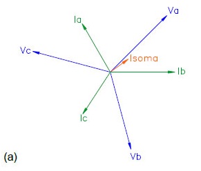
One of the techniques that allows the practical constraint shown is using the vectorial sum of the leakage current for the three bushings in a three-phase system. In an arrangement like this, the three leakage currents are out of phase by approximately 120º, and usually have the same order of magnitude, since, in principle, all three bushings have the similar capacitances and the voltages for the three phases are close to balanced. In this way, the sumo f the three leakage currents tends to a total sum value much smaller than any of the leakage currents taken individually, as shown in Figure 3.(a) for a given initial condition of capacitances and dissipation factors.
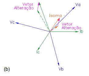
Figure 3 – Leakage currents in the three bushings of a three-phase system and their sum; (a) For a given initial; condition; (b) with change to the capacitance and dissipation factor for the phase A bushing.
Supposing that we now have a change in the capacitance and the dissipation factor of the bushing on phase A, as shown in Figure 3.(b), the Change Vector (Vetor Alteração – DI) that expresses the displacement of current Ia from its initial value to its final value is also reflected in the sum current, which is changed in relation to its initial value according to the same Change Vector DI.
This Change Vector is practically imperceptible when compared to the magnitude of the leakage current in phase A. However, the same is not true when this vector is compared to the sum current, which allows it to be detected, and therefore, also detects changes occurred in the impedance of the bushing in case of point.
By the above exposed, a few intrinsic characteristics to the method above are:
- An initial reference must be determined for the system’s currents, then these must be compared to the new online measurements, with a view to determining any changes occurred in the bushing’s capacitance and dissipation factor;
- Absolute values of capacitance and tangent delta of bushings are not measured, what is measured are the variations occurred in these parameters. However, once each bushings initial capacitance and tangent delta values are known (values present at the moment that the initial reference currents are is determined for the bushings), measuring their variations, allows current values to be calculated for capacitance and tangent delta;
- For new bushings, rated values for capacitance and tangent delta supplied by manufacturer of the equipment on the plaque can be used as the initial reference values. However, for bushings already in operation, it is advisable that when installing the online monitoring system, these parameters should be measured using the conventional methods, with bushings de-energized. This ensures that correct intial values will be used by the monitoring system.
2.3 – Safety of the online monitoring system
As exposed in the explanation above, leakage currents and sum currents are influenced not only by changes in the capacitance and tangent delta of the bushings, but also by changes in each bushing’s phase-ground voltage. This influence is eliminated by way of mathematical and statistical treatments performed on the measurements, reason for which the process for defining the initial reference currents is carried out in an adjustable time period of between 1 and 7 days after beginning of operation of the monitoring system. On the other hand, the process of measuring changes occurred, for the same reasons, has a response time constant of the same magnitude.
The bushing’s physical construct gives rise to a capacitive voltage splitter, as previously shown, with the lower portion of this splitter usually being shorted, grounding the bushing tap, so that its voltage in relation to ground is zero volts. In order to be able to measure the bushing leakage current, this grounding is then done through the leakage current measurement circuit. Due to this circuit’s low impedance, tap voltage in relation ground remains very close to zero. However, in case of accidental interruption of the measurement circuit, the capacitive voltage splitter would generate a voltage on the bushing of the tap which normally is higher than the dielectric rigidity of the tap in relation to ground, with a risk of damaging the bushing.
To keep this from happening, the bushing tap connection adaptor is provided with two voltage limiter devices connected in parallel, in a redundant configuration. These devices start conducing when the measurement circuit opens, creating a low impedance path for the leakage current, so that the voltage on the tap remains of few volts in relation to ground. Voltage limiter devices are not susceptible to wear of mechanical or electrical origins, which allows each one of them to individually carry, for indeterminate time, a minimum of 2.5 times the maximum leakage current found in the different bushing models found on the market.
In addition to this, voltage limiter devices act as protection against over-currents and over-voltages that develop on the tap of the bushing in the event of transitory over-voltages in the power system. This also every dielectric test to be performed on the bushing (for example, impulse voltages) with the on-line monitoring system connected and in operation.
3.0 – INSTALLING THE ON-LINE MONITORING SYSTEM
The bushing monitoring system deployed has a modular concept, being comprised of three main parts:
- Tap adapters – provide the electrical connection to the bushing taps, also ensuring their weatherproofing. They incorporate redundant protections against accidental rupture of the measurement circuit, preventing the tap from remaining open;
- Measurement Modules – receive the leakage currents from three bushings in a three-phase system, measure their currents and process them mathematically and statistically, delivering to the interface module the current capacitance and tangent delta values through a serial communication port;
- Interface Module – receives information through measurement modules and makes the available locally on the display of the device and remotely through output contacts for alarms, analog outputs (mA) and serial communication ports. Optionally, Interface Modules can also be connected to the company Intranet for remote access to readings.
In this application, the set up of the bushing monitoring system included the following components:
- Three 550kV and three 245kV bushings, all with voltage taps connected to Bushing Potential Devices (Dispositivos de Potencial de Bucha – DPB), in a bank of single phase auto-transformers;
- Three 550kV bushings with test taps, without a DPB connection, in a bank of single phase shunt reactors.
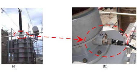
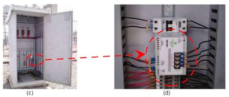
In the case of reactor banks, that do not use DPBs, connection to test taps was performed using Tap Adapters supplied by Treetech, as shown in Figure 4-(b). Bushing Adapters of the bushings in the bank’s three phases are then connected to the inputs of the Measurement Module installed on the Common Panel of the reactor bank, Figures 4-(c) and 4-(d).
Figure 4 – Bushing monitoring on single-phase reactor bank; (a) Reactors; (b) Tap adapter on 525kV bushing tap; (c) Common Panel for reactor bank; (d) Measurement Module for reactor bushings.
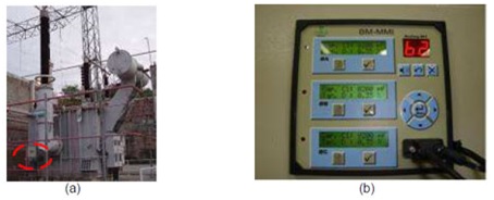
For the auto-transformer bank, Tap Adapters are not deployed, since as shown in Figure 5-(b), there are already Bushing Potential Devices connected to the taps of the bushings. Since the voltage output of a BPD is affected proportionally to the variations in capacitance C1 of the bushing to which it is connected, these voltages are employed as input signals for the Measurement Modules for the monitoring system, using this for coupling capacitors.
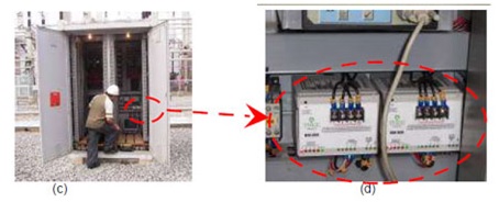
Therefore, for auto-transformer banks, two Measurement Modules are used: one that receives signals from the BPDs on the 550kV bushings and another that receives the signals from the 245kV bushing BPD. Both Measurement Modules are installed inside the Common Panel for the bank of auto-transformers, as shown in Figure 5-(c) and 5-(d).
A single Interface Module was employed for the auto-transformer bank and the reactors, initially installed on the auto-transformer bank’s Common Panel. Since the connection between Measurement Modules and the Interface Module is done out using an RS485 network (twisted pair metallic cables), the Interface Module was later moved to the substation Relay Room, about one hundred meters away from the equipment. The intention of this change was to create a link between the Interface Module and the Furnas intranet, already available in this room, without having to extend the intranet to the station yard, which would require the deployment of optical fiber link. Instead, the RS485 network that connects the modules of the monitoring system was taken to the Relay Room using a low cost, simple, twisted pair metallic cable. Figure 5-(b).
Figure 5 – Single-phase, auto-transformer bank bushing monitoring; (a) Auto-transformer with BPD; (b) Interface Module in Relay Room; (c) Common Panel of the auto-transformer bank; (d) Measurement Modules for bushings on the auto-transformers.
With the Interface Module connected to the Furnas intranet, there is remote access to all the information provided by the bushing monitoring system, such as present value and alarm actuations, from company offices, in the plant or out of it.
4.0 – RESULTS ACHIEVED
4.1 – Stability of measurements
In the case of the bank of reactors, where there is a direct connection between the tap Adapters and the Measurement Module, both capacitance and tangent delta are monitored for the 550kV bushings. The charts shown in Figure 6 show the typical behavior of these variables. It can be seen that the monitoring system offered stable readings, with variations on the order of 0.1% for capacitances and 0.1% (in absolute variation) for the tangent delta readings.
Figure 6 – Typical behavior of Capacitance and Tangent Delta readings on reactor bushings
In addition to showing that the insulation of these bushings did not display variation in the period, these results, also attest to the stability of the technique employed in performing the on-line monitoring, practically immune to the interference of the phenomenon usually found in power systems, such as phase-ground fluctuations, unbalances between phases and maneuver surges.
For the bushings on the auto-transformer bank, the output voltage of the Bushing Potential Devices (BPD) is used as input signal for the monitoring system. Therefore, any eventual variations on the output of the BPDs, caused by changes in temperature, for instance, can influence the readings of the on-line monitoring system. This fact becomes more evident in the tangent delta readings, due to the small magnitude of the dielectric loss currents for the insulation of the bushing as compared to capacitive currents. Capacitance readings, on the other hand and for the same reason, are little affected by variations occurring in the BPDs.
Thus, the 550kV and 245kV bushings of the auto-transformer bank are monitored only through their capacitance readings, and the tangent delta reading is not used. The typical behavior of this reading is shown in the chart of Figure 7, where, in spite of the variations caused by the BPDs, fluctuations under 0.2% in the capacitance reading are seen.
Figure 7 – Typical behavior of Capacitance readings measured on the 550kV bushings of auto-transformers
4.2 – Detection of defect in a 550kV bushing
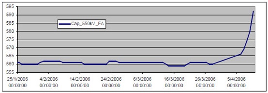
As previously mentioned, the on-line bushing monitoring was installed because of suspicion that existed in relation to a family of bushings. The suspicion was confirmed during the operation of the monitoring system, when na alarm for high capacitance rise was sounded for the 550kV bushing on Phase A of the auto-transformer, rising from 560pF to 594pF, or close to 6%, as shown by the chart on Figure 8.
Figure 8 – Increased Capacitance on 550 kV bushing of phase A autotransformer
Even more severe, however, was discovering a high rise rate for the capacitance, leading to the quick shut down of the bank. With the auto-transformer bank down, the off-line capacitance readings were taken, in addition to samples being taken for analysis of dissolved gases in laboratory. Samples were sent to the Furnas laboratory, in addition to the manufacturer of auto-transformers, both pointing to results similar to those shown below on table 1. The high concentrations of flammable gases found draw attention, in particular acetylene, with nearly 7000ppm, which confirmed the presence of an internal defect evolving in the bushing.
Gases dissolved in bushing oil for phase A of autotransformer
| Gas | H2 | O2 | N2 | CH4 | CO | CO2 | C2H4 | C2H6 | C2H2 | TGC |
| Content (ppm) | 7401 | 2100 | 47969 | 5477 | 2000 | 10665 | 4597 | 1728 | 6904 | 28107 |
The off line capacitance measurements also confirmed the alarm issued by the on line bushing monitoring, indicating the existence of short circuited insulation layers. These readings also showed tangent delta of 0.97% and capacitance of 853pF, higher to the readings obtained on-line. This difference in the readings is explained by the fact that the capacitance was undergoing a process of continued rise, which causes a time difference between the actual capacitance and the value shown by the on-line monitoring due to the required response time, as explained in item 2.3. In other words, if the bushing capacitance were to become stable at a given value, the value displayed by the on-line monitoring would reach this same value after the end of the response time.
5.0 – CONCLUSION
High voltage condenser bushings are an essential accessory for the operation of the different high voltage equipment items, such as power transformer and reactors. This article showed the principle of operation that allows on-line monitoring for this type of bushing, thus the experience of deploying this system on the bushings of a 550/245kV single-phase auto-transformer bank and single-phase 550kV reactors at the Serra da Mesa Plant.
During the operation, fluctuations observed in the on-line readings were on the order of up to 0.4% for capacitance and 0.13% for tangent delta (in absolute value, in the reactor bank where it is measured), allowing fairly sensitive alarm settings to be used. This led to the successful detection of a defect in evolution in the insulation of a 550kV bushing in one of the auto-transformers, allowing the equipment to be removed from service before the occurrence of a severe failure, probably resulting in an explosion of the bushing.
Thus it was shown in practice that on-line bushing monitoring can become an additional and reliable tool in accident prevention in this type of equipment, not only increasing the levels of reliability and availability for the power grid system and maintaining equipment integrity, but also increasing safety for people in the substations.


